Connection Map
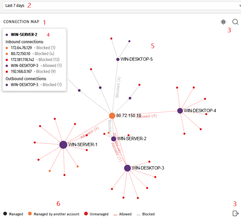
The Connection Map is a visual representation of connections between computers on the network that meet the conditions you configure in the Endpoint Access Enforcement settings.
For more information about Endpoint Access Enforcement, see Endpoint Access Enforcement settings.
Connection Map structure
-
Widget name (1).
-
Time selector (2): From the drop-down menu, select the time period for the data you want to see. See Connection Map settings.
-
Tools (3):
-
To find a computer or an IP address, click
 . See Connection Map settings.
 -
To save the Connection Map, click
 . See Connection Map settings.
-
-
Information panel (4): Point to a node. An information panel appears and shows information about connections for the node.
-
Graph (5): A graphical representation that uses nodes and arrows to show connections between computers and connection direction. It also shows the actions that Endpoint Access Enforcement took on connections, and the number of connections affected by the action. See Node and connection features.
-
Legend (6): A color system that shows managed and unmanaged computers, and lines for allowed and blocked connections.
Connection Map controls
-
Zoom: By default, the widget has a sufficient level of zoom to make sure you can see all nodes without having to move the graph. You can use your mouse wheel to zoom in and out on the Connection Map. Click
 to reset the zoom level.
 -
Filter by group: Depending on the number of computers or computer groups involved in connections, a large amount of data can be shown in the graph. To limit the amount of generated data, click the Filter by group icon
 next to the web notification icon
  . For more information, see Filtering results by groups.
 -
Move the graph: To move the graph, click and drag it in the appropriate direction. Click
to move the graph back to its initial position. -
Access the Connections identified by Endpoint Access Enforcement list: Click a computer node. The Connections identified by Endpoint Access Enforcement list opens filtered by the computer name or IP address.
See Endpoint Access Enforcement module lists and Node and connection features.
Connection Map settings
-
Time range. Select the time period for the data you want to see:
-
Last 24 hours
-
Last 7 days
-
Last month
-
Last year
-
-
Search tool. Click
. From the drop-down menu, select the name or IP address of the computer you want to find in the graph. -
Save graph. You can show or hide information layers in the graph, and save the graph. Click
. A drop-down menu opens and shows these options:-
Computers: Hides or shows graph nodes.
-
Connections: Hides or shows connection lines.
-
Computers labels: Hides or shows node labels.
-
Connections labels: Hides or shows connection line labels and the number of connections for each line.
-
Click Export.
-
Node and connection features
The Connection Map represents computers and connections through nodes, lines, and associated labels. See Connection Map.
Node colors
Nodes show information through their associated icons:
-
Purple: A managed computer.
-
Orange: A computer managed by another account.
-
Red: An unmanaged computer.
Node labels
Based on the type of computer, the node label shows the computer name or IP address.
-
Computer managed by the same account as the other end of the connection: The label shows the name of the selected computer.
-
Computer managed by a different account than the account that manages the other end of the connection: The label shows the IP address of the selected computer.
-
Unmanaged computer: The label shows the IP address of the selected computer.
See Endpoint Access Enforcement settings options.
Node size
-
Managed computer (purple node): The size of the node depends on the number of inbound and outbound connections.
-
Computer managed by another account (orange node): The size of the node depends on the number of inbound and outbound connections.
-
Unmanaged computer (red node): The size of the node depends on the number of outbound connections.
Connection lines
Connections between nodes are represented through lines and numbers.
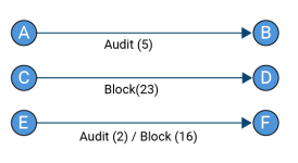
Line direction
-
Unidirectional line: The number on the line indicates all allowed or blocked connections between two nodes for the selected period.
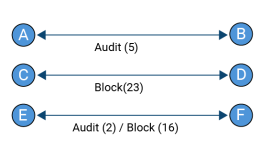
-
Bidirectional line: The number on the line indicates the total sum of allowed and blocked connections between two nodes, in both directions, for the selected period.
Line color
The color of the line indicates the action Endpoint Access Enforcement took on the connection. Red lines represent allowed connections in Audit mode. Gray lines represent blocked connections. See Endpoint Access Enforcement operating mode.